Tuesday, August 08 2017
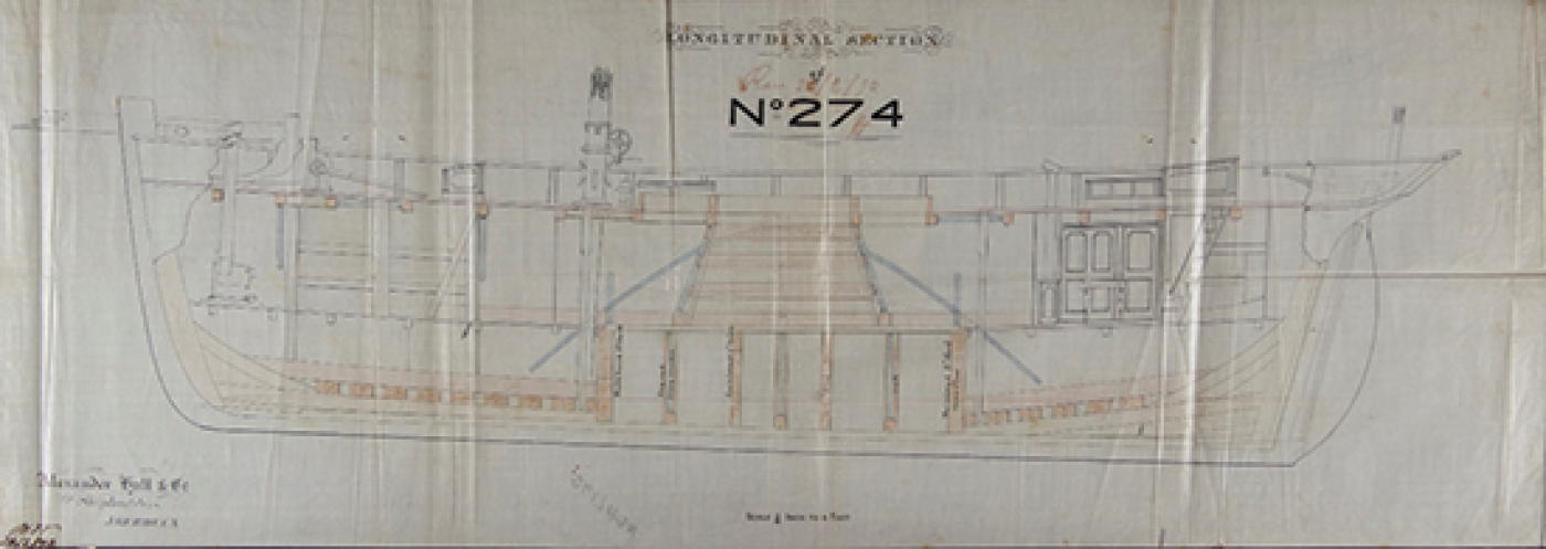
As part of my university degree I was required to find a client project to do as the very first project of my final year. Over the summer I contacted a number of different clients to ascertain if any wanted a model made. I was put in touch with the Curator of Maritime History & Heritage at the Lloyd's Register Foundation (LRF) in London who was able to give me access to their archived ship plans. It was a perfect opportunity to make a different model of part of our history and the history of Lloyd's Register. I met my client in London and we went to the archive store called the Brass Foundry in Woolwich. We spent the day searching through boxes of beautiful plans most of which were over 100 years old trying to find an old vessel that was entirely or mostly wooden in construction. Many of the plans were not complete sets and I needed as much information as possible on the vessel, to make it historically accurate. We found some plans of a vessel from 1872 that had both a longitudinal and a mid-ship section plan. It was the most detailed plan we had found and the more we looked into the plans the more interesting features became apparent. We quickly became intrigued to find more about the vessel, Robert Miller, and decided it was perfect for my project.
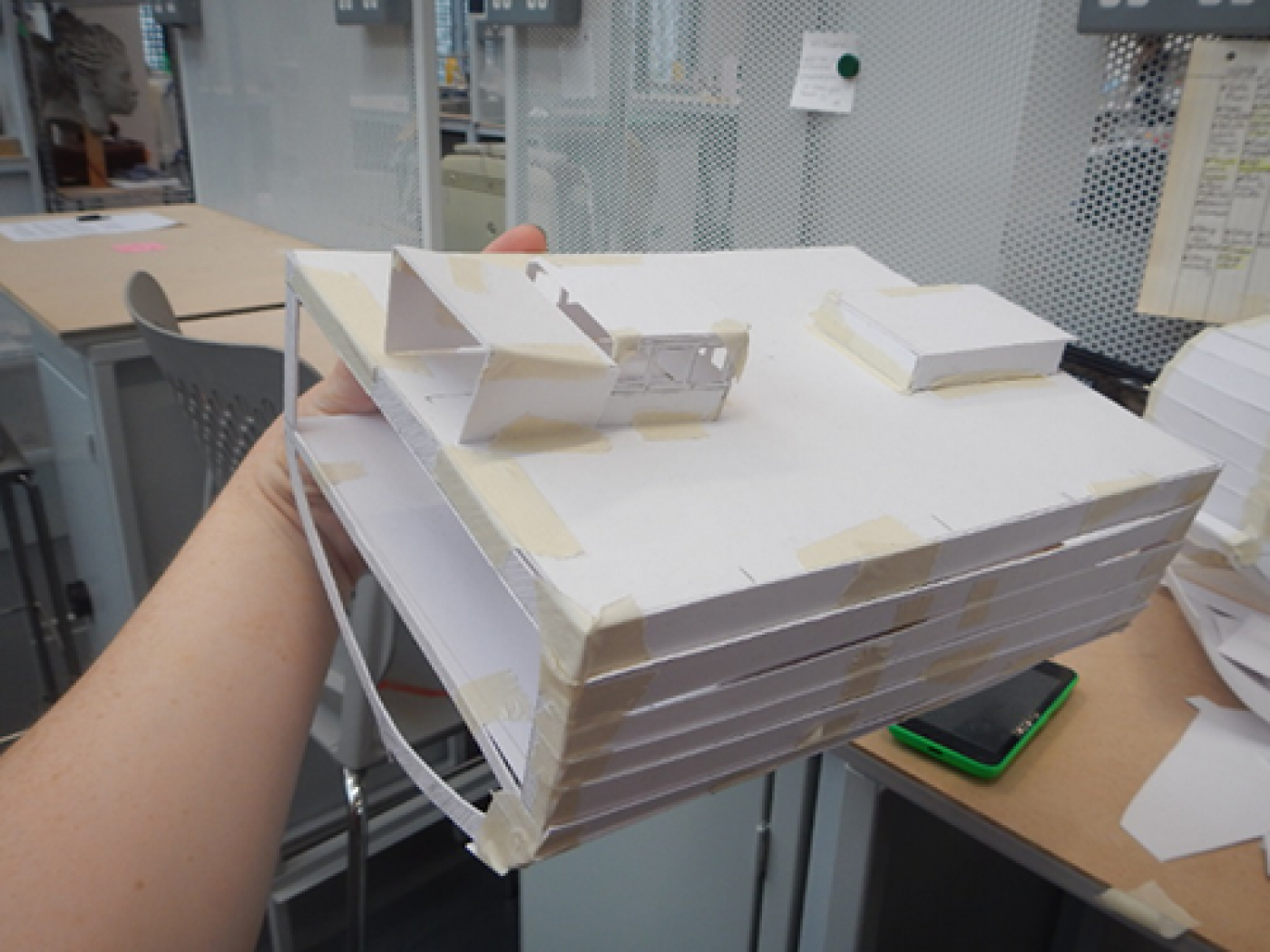
After some time, I returned to LRF's London office to do further research into the type of vessel, as we came to find it was called a welled fishing smack, an old type of fishing vessel that was quite unique. Much of the ship's method of fishing depended on its interior, so I was keen to make a sectional model that showed both the interior and exterior of the vessel. I was inspired by such models that had been made of HMS Victory that displayed each deck and where the guns and storage barrels were stowed. However, my project only spanned the time of 8 weeks so in order to complete the model I had to make the project a manageable size. Armed with research from a day spent at the LRF library, a trip to look around HMS Victory in Portsmouth and scans of the plans (that took several days to naturally flatten due to their age), I started working on quick sketch models to gain an idea of scale and which part of the ship I thought would be interesting. During the project I kept in close contact with my client checking at each stage that she was happy with my decisions and progress. I did several card sketch models, at varying scales and sections of the vessel to see which part would be the most interesting. We decided that a sectional model containing a cabin, skylight and part of the well would make a good model that would communicate the purpose of the ship while showing off its more interesting features.
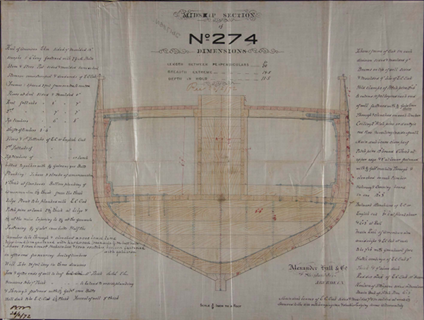
Robert Miller was built in 1872, a welled fishing smack owned by the Shetland Fishing Company. She measured 82 tons, was 70 feet 9 inches in length, 19 feet 8 inches in breadth and 12 feet 3 inches in depth. All of the specific information on the Robert Miller was recorded by Lloyd's Register on their survey of the ship in 1872. This was highly useful when scaling the plans correctly. I did broader research into the welled fishing smack, its function and any other information I could find on that type of vessel. One of the most interesting features of Robert Miller is its well. In the centre of the vessel there is a shoot which leads to a section at the bottom contained by several bulkheads, which are thick strong dividing walls inside a vessel. With the well, an entire section is sealed off and holes are bored into the planks of the vessel to allow water to fill and flow through that section of the ship. This well is then used to store fish that are caught at sea, keeping them alive so that they could sell for a higher price due to their freshness when brought to market.
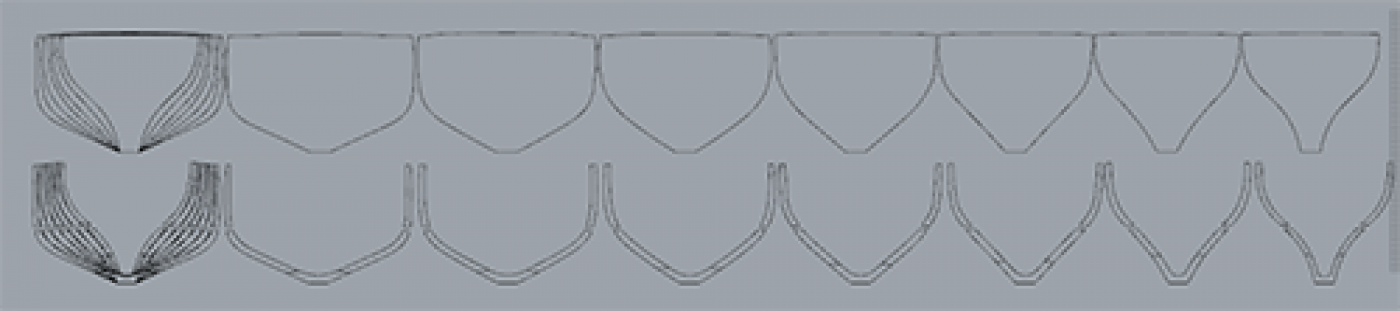
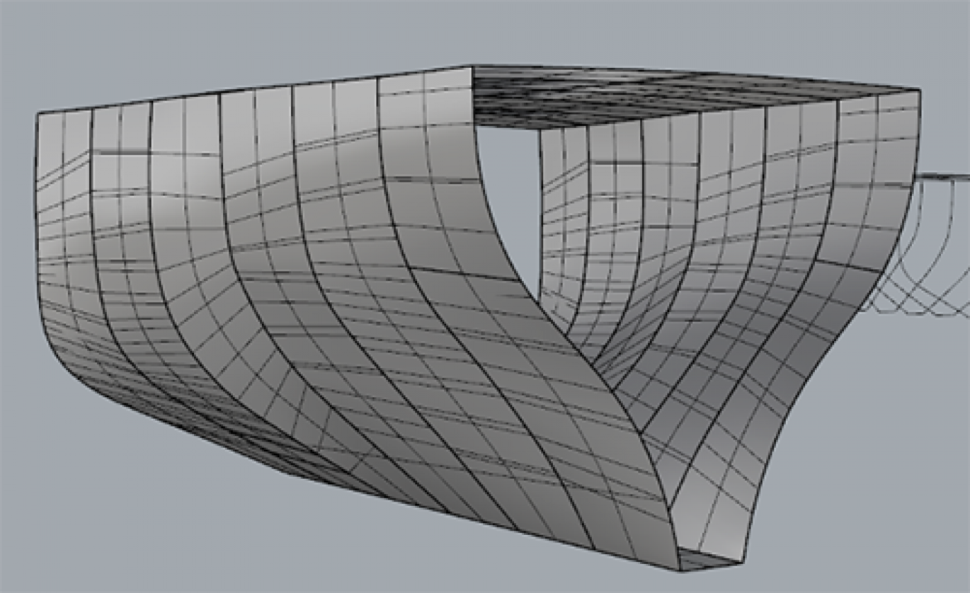
I found other plans of similar vessels that aided me in making a 3D model of the ship using CAD (computer aided design). I did this in Rhino 5, a 3D modelling program and spent a week getting all the decklines and the shape of the ship correct as this would make or break my model. I drew out all of the transverse sections using a section plan for another ship as a guide. I then used a tool called a loft tool to add a surface that follows all these sections. I then spent a great deal of time tweaking the shape of each section to get the shape of the vessel flowing correctly, as I did not have an exact plan of all the sections and the original ones that I drew out were not perfect.
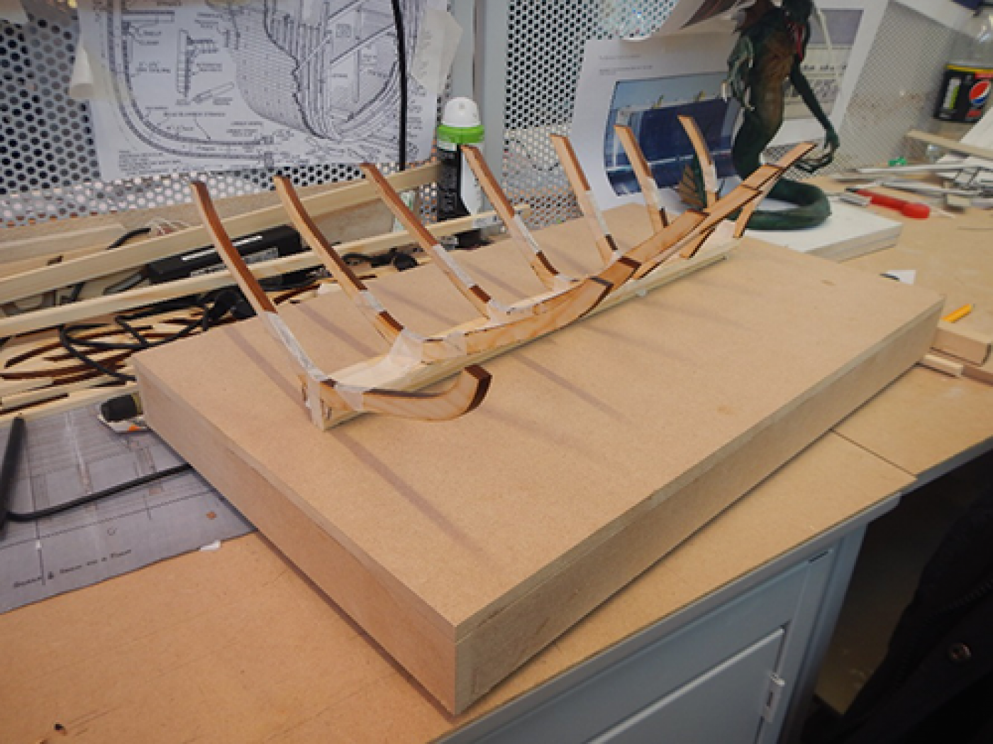
As I was 3D modelling the vessel I started to plan out what materials I wanted to make the model out of and consulted my client on what she wanted. I went out and bought these materials, I mainly used pine wood, timber and MDF. The first step of starting the framework for the model was making the keel and laser cutting all of the frames of the hull, as I intended to make a plank on frame model, which involves creating a framework and bending strips of wood around that framework to create the hull. Laser cutting is a process that involves using drawings from a CAD program like Rhino and using a laser to cut the shapes out of a material. This type of technology is highly useful when dealing with complex shapes that need to be accurate or involves cutting shapes that would not be easily cut on hand machines.
Once I had laser cut all the pieces I dry fitted them, which simply involved sticking them together with tape to check they were correct. This was a very exciting start to the project as I could already see the hull starting to take shape and that I had done the CAD modelling correctly. After this stage, already 2-3 weeks into my 8 week project, the model started coming together very quickly and I was getting closer to my deadline. Keeping as close to the original plans as possible I went on to create some bulkheads that keep the water in the well contained. I did lots of material testing using dyes and other wood varnishes to achieve different looks for different parts of the vessel. I checked all of this with my client before proceeding to treat and dye parts of the final model to represent different types of wood used in the original construction.
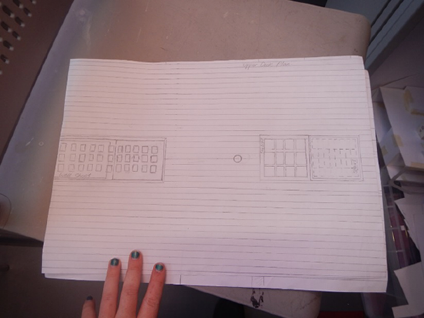
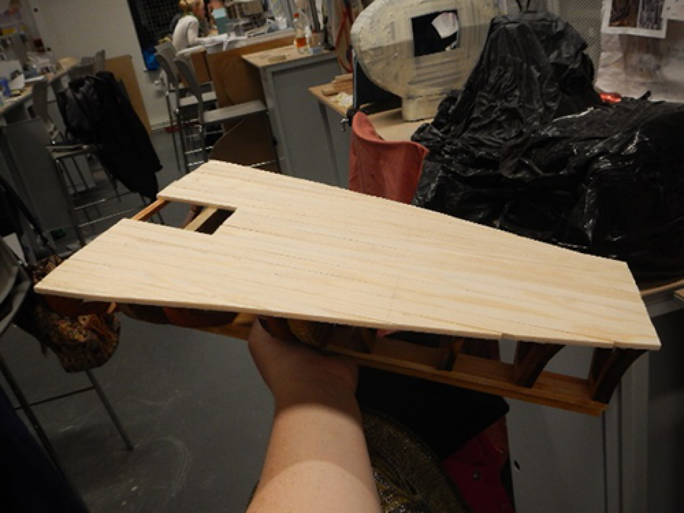
The model quickly started to take shape as I worked my way from the keel up to the first deck. As an aid to making the decks and organising the interior I drew up plans of the two decks from the information I had on Robert Miller and similar vessels. I used the mid-ship plan to work out what width each plank was on the two decks as each deck had a different width of plank. I made the first deck by cutting strips of pine equally on a band saw. I then stuck all of the planks down onto a spare piece of MDF and cut them on the band saw into the correct shape of the deck using a plan that I drew onto the MDF. I sanded all of the planks together on a sanding machine until the deck was the correct shape to fit onto the frames. I finally stuck down the deck onto the frames piece by piece using clamps to secure each plank as they dried.
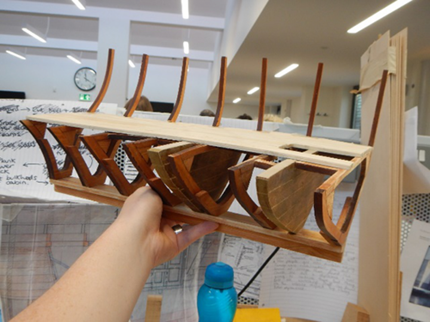
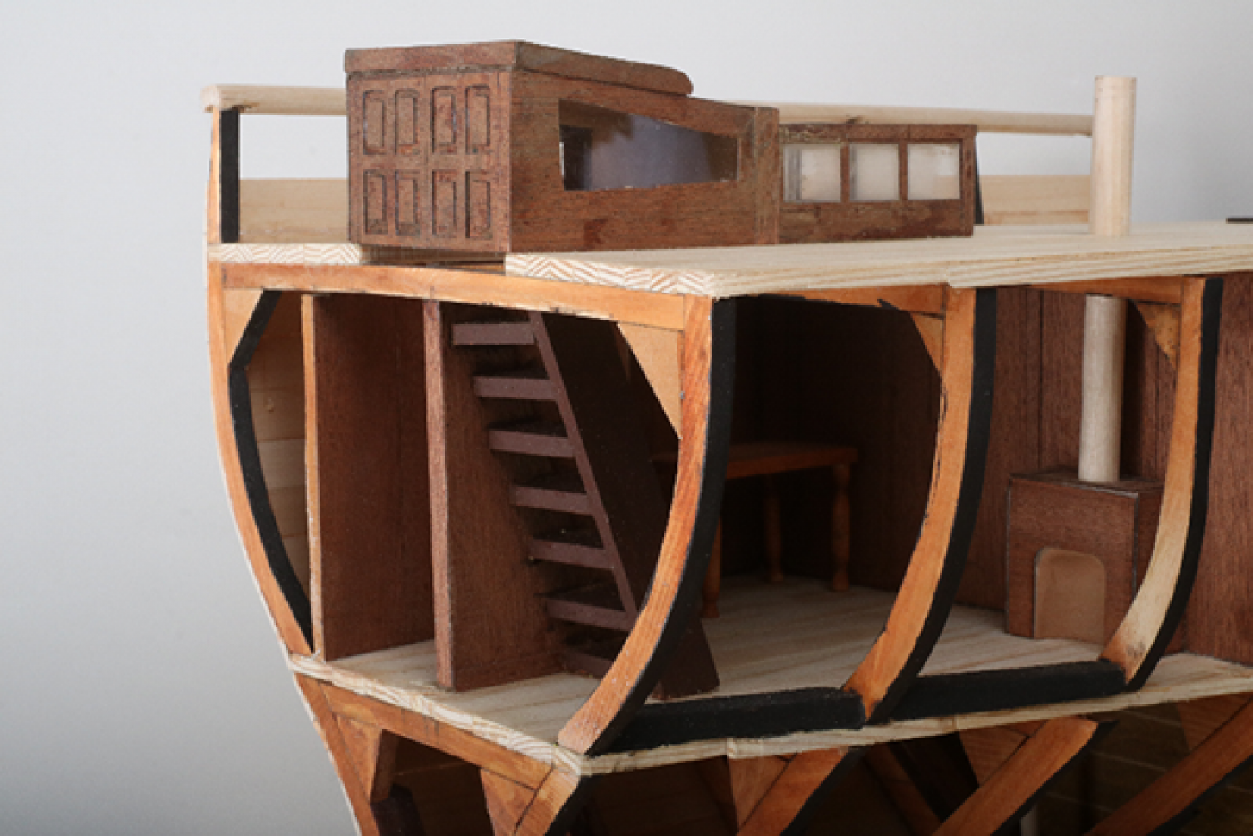
The next stage of construction involved making all the walls for the interior, before sticking them down I had to check that they were the correct fit to go underneath the upper deck. In order to check this I stuck together the rest of the frame work that supports the upper deck. I clad the interior cabin walls with veneer that I laser engraved using CAD drawings. Once I had stuck on all the veneer and stuck the walls together I fixed them onto the lower deck. The next part was to make the well funnel and adding in details to the crew cabin such as a ladder that leads to a hatch on the upper deck, and also a fireplace. All of these details were present on the plans, so I thought they would make the model more accurate as well as giving the model some interesting details.
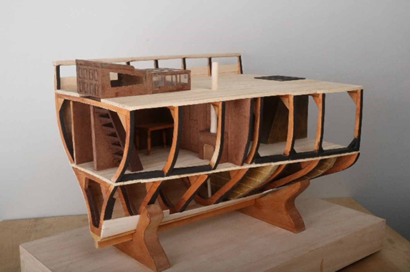
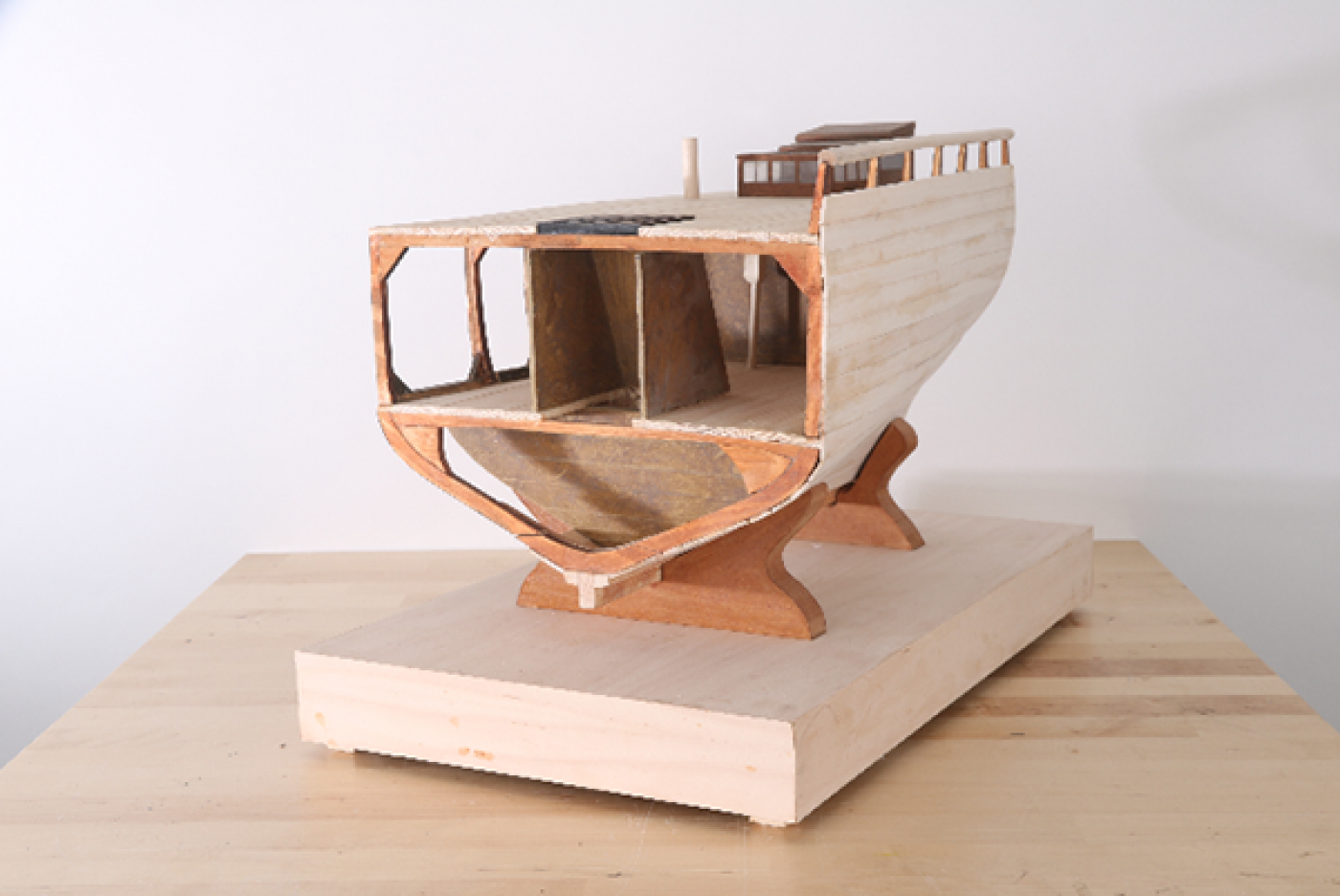
After finishing all the interior cabin details and the well funnel I stuck down the remaining frames onto the lower deck. I could then begin constructing the upper deck in much the same way as the lower. By this time I was quite far through my project and started to think about what method of planking I was going to use I knew this would be time consuming and I had to get started as soon as I had finished the upper deck. I cut out lots of strips of wood ready for the planking and decided to soak the wood in water to make the planking process easier. I spent a long time planking the exterior of one side of the model as the process involved leaving the planks to soak in water for a time, placing them on the framework, clamping them, leaving them to dry, and finally gluing them in place. I started this process doing one plank at a time, but soon realised I could clamp two planks at once to save time. Also as I worked I had to strip down the ends of some of the planks to keep their longitudinal lines parallel so that the planking looked correct.
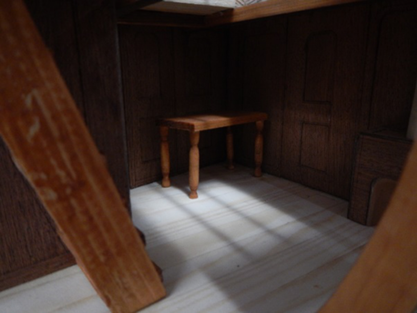
After one side of the model was planked I had to put all the finishing touches on the model, such as the skylight on the upper deck, the hatches for the well and stairs. I sanded the planks on the side of the model smooth and added bulwarks (a railing) onto the top deck on one side. I left the other side of the model free from planking in order to see inside the vessel and gain an understanding of its construction and use. One of my favourite features of the finished model is the lighting in the cabin, when there is light shining through the skylight an eerily realistic shadow is cast inside the cabin giving the model a touch of realism. As another finishing touch I made a tiny table using the wood lathe for the legs, as on the original plans a table had been drawn inside the cabin.
The Heritage & Education Centre would like to extend its thanks to Sarah for her excellent model and the care and attention to detail she provided.